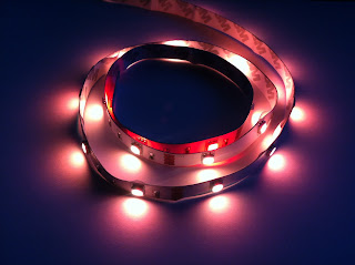
Este produto foi desenvolvido para atender aplicações que requerem iluminação contínua em superfície plana ou curva. Pode ser facilmente montado em qualquer aplicativo (não-condutor) com fita dupla-face, altamente flexível: slim em tamanho compacto, cabe em qualquer espaço estreito ou curvas. Baixo consumo de energia, super-brilhante, e funciona com temperatura baixa. Já tem conector DC soldado, pronto para ser ligado e funcionar. LED de alta qualidade, intensidade elevada e confiabilidade, longa vida útil> 50.000 horas.
Pode ser ligado ao microcontrolador para criar diferentes efeitos, podendo usar o PWM para mudar intensidade do brilho de cada cor e assim obter todas as cores RGB. O exemplo a seguir é usando o software amblone, que copia as cores do seu monitor na fita de LED, criando um efeito muito bonito, já usado pelas grandes fabricantes de televisores como Ambilight da Philips.
Características:
Tamanho: 1 metro
Core: RGB
Como funciona:
Baixe o amblone:
http://amblone.com/download
Grave esse código em seu Arduino:
// Amblone code for the Arduino Mega
// Author: Bart van der Drift
// License:
// Anyone is free to change, redistribute or copy parts of this code
// as long as it is not for commercial purposes
// Please be so kind to pay credit where due
//---------------------------------------------------------------------------
//---------------------------------- DEFINES --------------------------------
//---------------------------------------------------------------------------
// Flags for the USB communication protocol
#define C_SF1 0xF1 // Startflag for 1-channel mode (1 RGB channel)
#define C_SF2 0xF2 // Startflag for 2-channel mode (2 RGB channels)
#define C_SF3 0xF3 // Startflag for 3-channel mode (3 RGB channels)
#define C_SF4 0xF4 // Startflag for 4-channel mode (4 RGB channels)
#define C_END 0x33 // End flag
#define C_ESC 0x99 // Escape character
// States for receiving the information, see the flow chart for more info
#define S_WAIT_FOR_SF 0
#define S_RECV_RGB 1
#define S_RECV_RGB_ESC 2
//---------------------------------------------------------------------------
//--------------------------- FUNCTION DECLARATIONS -------------------------
//---------------------------------------------------------------------------
// Receives bytes and returns true if a valid packet was received
boolean PacketReceived();
// Uses the rgb values to set the PWMs
void SetPWMs();
//---------------------------------------------------------------------------
//--------------------------- VARIABLE DECLARATIONS -------------------------
//---------------------------------------------------------------------------
int pulse = 0;
// State we are in: one of the S_* defines
int State = 0;
// The payload of a received message
int Payload[32];
// The amount of RGB values we have received
int ByteCount = 0;
// The character we received
int Recv;
// The amount of RGB channels we are using
int ChannelMode;
// PWM pins for channel 1
int r1_pin = 2;
int g1_pin = 3;
int b1_pin = 4;
// PWM pins for channel 2
int r2_pin = 5;
int g2_pin = 6;
int b2_pin = 7;
// PWM pins for channel 3
int r3_pin = 8;
int g3_pin = 9;
int b3_pin = 10;
// PWM pins for channel 4
int r4_pin = 11;
int g4_pin = 12;
int b4_pin = 13;
//---------------------------------------------------------------------------
//----------------------------- IMPLEMENTATIONS -----------------------------
//---------------------------------------------------------------------------
void setup() {
// initialize the serial communication
Serial.begin(256000); // opens serial port, sets data rate to 256000 bps
TCCR0B = TCCR0B & 0b11111000 | 0x2;
TCCR1B = TCCR0B & 0b11111000 | 0x2;
TCCR2B = TCCR0B & 0b11111000 | 0x2;
TCCR3B = TCCR0B & 0b11111000 | 0x2;
TCCR4B = TCCR0B & 0b11111000 | 0x2;
State = S_WAIT_FOR_SF;
}
//---------------------------------------------------------------------------
void loop()
{
if (Serial.available() > 0) {
if (PacketReceived()) {
SetPWMs();
}
}
}
//---------------------------------------------------------------------------
boolean PacketReceived() {
Recv = Serial.read();
switch (State) {
case S_WAIT_FOR_SF:
// =============================== Wait for start flag state
switch (Recv) {
case C_SF1:
// Start flag for 1-channel mode
ChannelMode = 1;
State = S_RECV_RGB;
ByteCount = 0;
return false;
case C_SF2:
// Start flag for 2-channel mode
ChannelMode = 2;
State = S_RECV_RGB;
ByteCount = 0;
return false;
case 243://C_SF3:
// Start flag for 3-channel mode
ChannelMode = 3;
State = S_RECV_RGB;
ByteCount = 0;
return false;
case C_SF4:
// Start flag for 4-channel mode
ChannelMode = 4;
State = S_RECV_RGB;
ByteCount = 0;
return false;
default:
// No action for all other characters
return false;
}
break;
case S_RECV_RGB:
// =============================== RGB Data reception state
switch (Recv) {
case C_SF1:
// Start flag for 1-channel mode
ChannelMode = 1;
State = S_RECV_RGB;
ByteCount = 0;
return false;
case C_SF2:
// Start flag for 2-channel mode
ChannelMode = 2;
State = S_RECV_RGB;
ByteCount = 0;
return false;
case C_SF3:
// Start flag for 3-channel mode
ChannelMode = 3;
State = S_RECV_RGB;
ByteCount = 0;
return false;
case C_SF4:
// Start flag for 4-channel mode
ChannelMode = 4;
State = S_RECV_RGB;
ByteCount = 0;
return false;
case C_END:
// End Flag
// For each channel, we should have received 3 values. If so, we have received a valid packet
if (ByteCount == ChannelMode * 3) {
State = S_WAIT_FOR_SF;
ByteCount = 0;
return true; // <------------------------ TRUE IS RETURNED
}
else {
// Something's gone wrong: restart
State = S_WAIT_FOR_SF;
ByteCount = 0;
return false;
}
case C_ESC:
// Escape character
State = S_RECV_RGB_ESC;
return false;
default:
// The character received wasn't a flag, so store it as an RGB value
Payload[ByteCount] = Recv;
ByteCount++;
return false;
}
case S_RECV_RGB_ESC:
// =============================== RGB Escaped data reception state
// Store the value in the payload, no matter what it is
Payload[ByteCount] = Recv;
ByteCount++;
State = S_RECV_RGB;
return false;
}
return false;
}
//---------------------------------------------------------------------------
void SetPWMs() {
// Channel 1
analogWrite(r1_pin, Payload[0]);
analogWrite(g1_pin, Payload[1]);
analogWrite(b1_pin, Payload[2]);
// Channel 2
if (ChannelMode > 1) {
analogWrite(r2_pin, Payload[3]);
analogWrite(g2_pin, Payload[4]);
analogWrite(b2_pin, Payload[5]);
}
else {
// turn the rest to 0 (black)
analogWrite(r2_pin, 0);
analogWrite(g2_pin, 0);
analogWrite(b2_pin, 0);
analogWrite(r3_pin, 0);
analogWrite(g3_pin, 0);
analogWrite(b3_pin, 0);
analogWrite(r4_pin, 0);
analogWrite(g4_pin, 0);
analogWrite(b4_pin, 0);
}
// Channel 3
if (ChannelMode > 2) {
analogWrite(r3_pin, Payload[6]);
analogWrite(g3_pin, Payload[7]);
analogWrite(b3_pin, Payload[8]);
}
else {
// turn the rest to 0 (black)
analogWrite(r3_pin, 0);
analogWrite(g3_pin, 0);
analogWrite(b3_pin, 0);
analogWrite(r4_pin, 0);
analogWrite(g4_pin, 0);
analogWrite(b4_pin, 0);
}
// Channel 4
if (ChannelMode > 3) {
analogWrite(r4_pin, Payload[9]);
analogWrite(g4_pin, Payload[10]);
analogWrite(b4_pin, Payload[11]);
}
else {
// turn the rest to 0 (black)
analogWrite(r4_pin, 0);
analogWrite(g4_pin, 0);
analogWrite(b4_pin, 0);
}
}
//---------------------------------------------------------------------------
E divirta-se:


Nenhum comentário:
Postar um comentário